


Desktop Aviator HOME Page
International Shipping Info


Soldering and Wiring the 2410 Circuit Board
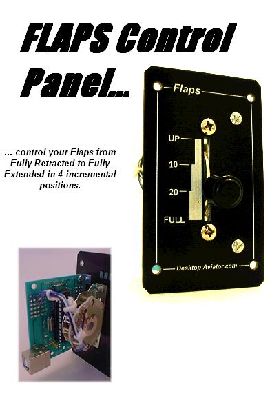
To increase the Realism of our flight sim cockpit, we wanted something other then a Paddle switch with a spring return to control our Flaps. We wanted something to emulate the flaps control lever found on Cessna's 172, Mooney, Beechcraft aircraft with descreet positioning that allows you to set your flaps in incremental settings from Fully Retracted to Fully Extended. The Model 2530 is the results of our efforts. Compatible with FS2002, FS2005, FSX, FSUIPC & X-Plane.
The 2530 is a small FLAPs Controller that is flush mounted to your aircraft cockpit. It utilitizes a 4 position Lever Switch that allows its internal computer chip to emulate the positioning of the flaps as seen on many Flight Sim programs.
The 2530 is a small FLAPs Controller that is flush mounted to your aircraft cockpit. It utilitizes a 4 position Lever Switch that allows its internal computer chip to emulate the positioning of the flaps as seen on many Flight Sim programs.
Come Check it Out!
Click HERE
Click HERE
Thank you for purchasing our Model 2410 Mounting Board. The 2410 provides a safe, convient and economical way to solder wires to the fragile terminals on your Single Rotary and the Dual Rotary Encoder Switch (with or without the internal normally open push switch).
By soldering the encoder switch to the 2410 pcb, you provide a steardy platform to connect the #28 stranded wires from the switch to any number of host USB Interface boards such as our Model 2090 and the 2095A.
By soldering the encoder switch to the 2410 pcb, you provide a steardy platform to connect the #28 stranded wires from the switch to any number of host USB Interface boards such as our Model 2090 and the 2095A.
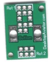
The 2410 is a double sided circuit board with plated through holes. In other words; when soldering a wire or encoder switch terminal on one side, it will also be soldered on the opposite side at the same time. This makes for easier mounting and soldering of the wires and switch.
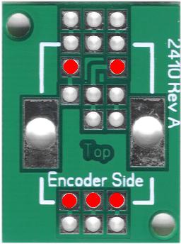
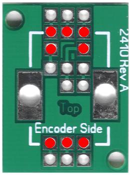
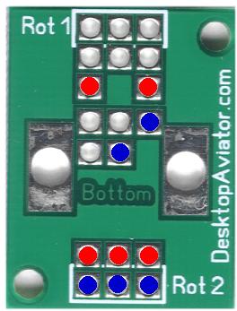
On the circuit board, you can see the wording "Encoder Side" and "Bottom". When are installing a single or dual rotary encoder switch; it is THIS side that the switch is mounted and soldered.
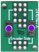
The 2410 also provided larger holes on either side of the board. These are the holes where the mounting tabs on the encoder switch are inserted.
On the circuit board, you can see the wording "Encoder Side" and "Bottom". When are installing a single or dual rotary encoder switch; it is THIS side that the switch is mounted and soldered.
The 2410 also provided larger holes on either side of the board. These are the holes where the mounting tabs on the encoder switch are inserted.
Mounting Holes.
Solder encoder
switch TABs Here
Solder encoder
switch TABs Here


Mounting Tabs on encoder switch

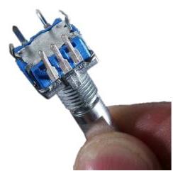
Rotary Encoder Switch - Rear
Overview of the 2410
Mounting a Standard Rotary Encoder Switch

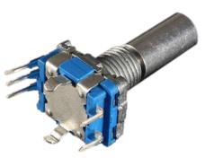
A standard 11mm Rotary Encoder switch has 3 fragile terminals; 5 terminals if the switch has the internal normally open switch (this switch is closed when you push on the shaft)
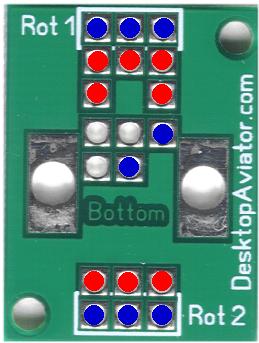
The photo of the circuit board (to the left) shows, in RED, where the 5 terminals (or 3 terminals) must be inserted. The switch's mounting tabs will also line-up with the 2410's holes.
Note the Text "Encoder Side". This is the side the switch is to be mounted
Note the Text "Encoder Side". This is the side the switch is to be mounted
Mounting a Standard Rotary Encoder Switch
Mounting a Dual Rotary Rotary Encoder Switch

Mounting a Dual Rotary Encoder Switch is just as easy as the standard switch, except you are now working with 8 terminals instead of 5.
So once again, the Dual Encoder Switch is mounted on the side marked
So once again, the Dual Encoder Switch is mounted on the side marked
"Encoder Side". The 8 RED circles indicate where the switch is to be inserted. When inserted carefully flip the assembly over and solder the terminals and TABs in place.
A small vise can help you with the soldering.
A small vise can help you with the soldering.
With the assembly flipped, place it in the vise and carefully close the vise on the body of the encoder switch, just enough to hold the switch and board without any movement. Ther procedure with the soldering.
Soldering the Wires to the 2410 Board (Single Encoder Switch)
Now, lets flip the 2410 board over and solder the wires. For this wiring, I suggest using DTA's
3-pin Extension Cables (available on the PARTS Page).
3-pin Extension Cables (available on the PARTS Page).
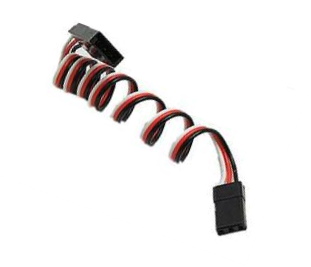
3-Pin Extension Cable 12 inch length
Cut off the MALE Connector
and solder it to the 2410 Board
and solder it to the 2410 Board

FEMALE Connector to 2090 or 2095A Board

Solder this side to the
BLACK wire on the
Extension Cable
BLACK wire on the
Extension Cable
Solder this side to the
RED wire on the
Extension Cable
RED wire on the
Extension Cable
Solder this side to the
WHITE wire on the
Extension Cable
WHITE wire on the
Extension Cable


These 2 wires connect to the internal Normally Open Switch. Can be connected to the 2090 or the 2095a boards as per the instruction page on each
The 3-pin Extension Cables can be used for both the Standard and Dual Rotaty Encoder Switches
Soldering the Wires to the 2410 Board (Dual Rotary Encoder Switch)
Solder this side to the
WHITE wire on the
Extension Cable
WHITE wire on the
Extension Cable
Solder this side to the
RED wire on the
Extension Cable
RED wire on the
Extension Cable
Solder this side to the
BLACK wire on the
Extension Cable
BLACK wire on the
Extension Cable
Solder this side to the
BLACK wire on the
Extension Cable
BLACK wire on the
Extension Cable
Solder this side to the
RED wire on the
Extension Cable
RED wire on the
Extension Cable
Solder this side to the
WHITE wire on the
Extension Cable
WHITE wire on the
Extension Cable


These 2 wires connect to the internal Normally Open Switch. Can be connected to the 2090 or the 2095a boards as per the instruction page on each


RED Dots indicate the encoder switch terminals on the board
RED Dots indicate the encoder switch terminals on the board
The soldering of the 2410 board with a Dual Rotary Encoder Switch mounted is basically the same as for the single; we just add a second 3-pin Extension Cable.
When complete, either or BOTH Encoder Asemblies can be connected to the Encoder Switch inputs of the 2090 or the 2095A Board.
When complete, either or BOTH Encoder Asemblies can be connected to the Encoder Switch inputs of the 2090 or the 2095A Board.
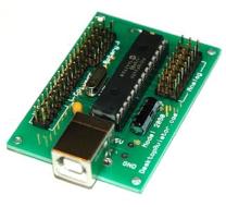
The 2090 Board
Connect the soldered 3-pin Extension Cables HERE