

Thank you for your purchase of our Model 2980 Parking Brake Panel with
Amber LED lighting.
The Model 2980 is compatible with FSX/FSUIPC, FSX-SE, Prepar3d,
X-Plane 10/11 and MS2020
Amber LED lighting.
The Model 2980 is compatible with FSX/FSUIPC, FSX-SE, Prepar3d,
X-Plane 10/11 and MS2020
Desktop Aviator HOME Page
International Shipping Info
Programming the
2980 Parking Brake
2980 Parking Brake

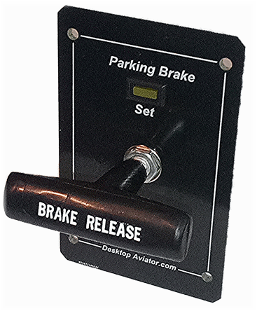
Thank you for your purchase of our new Model
2980 USB Parking Brake. The 2980 is compatible
with FSX, FSUIPC, MS2020, Prepar3d and X-Plane.
You can easily increase the realism of your flight
by adding this Parking Brake Panel. Designed with
the look and feel of a REAL Aircraft Parking Brake,
the 2405 adds the REALISM of Flight but without
the HIGH Cost.
Instructions
Connect the Parking Brake to an Available USB
Port on the back of your computer. The 2980 is
sensed as a standard HID Joystick, so Driver
software is automatically installed by your computer
for easy Plug-'n-Play installation.
For FSX and FSX Steam Edition - FSUICP is also Supported
With the Parking Brake connected and FSX loaded and running, goto the SETTINGs Window. Look at Controller Type for the Parking Brake link. Then click on Buttons/Keys. First, you need to DELETE all default settings seen in the window. When DELETED, find and click on Brakes Apply / Brakes Release or similiar setting. Click on New Assignment. Then pull the Parking Brake Handle out. You should see Button 31 appear in the window. Then click OK. Make sure that the Repeat Bar is all the way to the RIGHT. Then click OK.
When the handle is in, Button #32 will light steady (Break Released).
For X-Plane 10/11
With the Parking Brake connected and X-Plane 10 loading and Running, goto the SETTINGs window. Pull the Handle out. note a small check mark appears on the left side of the screen. On the right side look for and click on Flight Controls. Under Flight Controls, look and click on Parking Brake Set / Parking Brake Release or similiar setting. Then exit setting window.
P3D
With the Parking Brake connected to your P3D software, configure the
2980 to:
Parking Brake Release
Parking Brake Apply
or similar.
Please Note: The Parking Brake Handle is Press-Fitted onto the shaft of the Push/Pull switch and can not be removed. If you try to remove the handle, you will break the switch null and Voiding any Warrenty. DTA will not be held responsible for any breakage of this type. If broken, standard repair fees and return shipping cost will be imposed.
Wiring the Optional Toggle (or Rocker) Switches
Unlike the Classic 2405 PB, the new 2980 supports up to 14 Single Pole Single Throw Toggle and or Rocker switches. With your purchase of the 2980, we also supply Seven 3-pin female connectors.
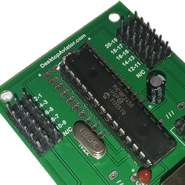
To the Right is a photo of the Interface board for the 2980. Note that there are two 3x6 Male Connector Header pins. These are broken down into J1 and J2 Group.
All Center pins are Common Ground, while the pins to the left and right of the ground are control inputs where the terminals of the toggle switches are soldered to.
Below is shown the wiring of 2 toggle switches. To access the full 14 inputs, you need to wire 7 assembles.
When wired, just place the 3-pin connector into the interface board's J1 and or J2 headers.


J1
J2
| 2-1 | Not Available |
| 4-3 | Not Available |
| 6-5 | Not Available |
| 7-8 | 14-13 |
| 10-9 | 12-11 |
| Not Available | Not Available |
Available Inputs
J1 J2
With the switch assemblies complete and inserted into the Interface board, all you need do now is to configure the switches to the Needed Flight Function.
Example:
Landing Lights on
Landing Lights off
ect
Example:
Landing Lights on
Landing Lights off
ect