
Thank you for your purchase of our Model 2120 USB to 20 Button Pulse Generator. The Switch Assignments are involved but can be easily accomplished with the help of the following information.
If you have any comments or need additional information on the use of the
USB to 20 Button Pulse Generator, please write us at:
Support@DesktopAviator.com
If you have any comments or need additional information on the use of the
USB to 20 Button Pulse Generator, please write us at:
Support@DesktopAviator.com
Desktop Aviator HOME Page
International Shipping Info
Wiring and Installing the 2120 Pulse Generator
INSTALLATION
Installing the USB INTERFACE requires very little time. All you need is an unused USB Port. Additional Ports can be added to your computer by using a device called a USB Hub. These Hubs can be purchased for as little as $20.00 in the Internet.
Just plug a USB Cable Series "B" into the jack on the
2120, then into the USB Port on your computer. The
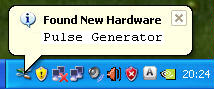
computer will sense the Adapter and load the required
software for its proper operation. The 2120 will be
sensed as "Pulse Generator Model 2120". That's all
there is to the installation.
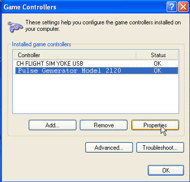
To verify that you computer has accepted the Interface, you can goto the "Game Controller" window. To do this, just click on "START" (located in the lower left hand corner of the computer's monitor); then click on "Control Panel"; then "Game Controller". Your computer should display the following:
Installing the USB INTERFACE requires very little time. All you need is an unused USB Port. Additional Ports can be added to your computer by using a device called a USB Hub. These Hubs can be purchased for as little as $20.00 in the Internet.
Just plug a USB Cable Series "B" into the jack on the
2120, then into the USB Port on your computer. The
computer will sense the Adapter and load the required
software for its proper operation. The 2120 will be
sensed as "Pulse Generator Model 2120". That's all
there is to the installation.
To verify that you computer has accepted the Interface, you can goto the "Game Controller" window. To do this, just click on "START" (located in the lower left hand corner of the computer's monitor); then click on "Control Panel"; then "Game Controller". Your computer should display the following:

Highlight "Pulse Generator Model 2120" then click "Properties"
Wiring Your Model 2120
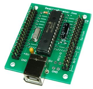
Below is a photo showing the 2120 Board with its J1 and J2 Headers. It is here (J1/J2) where we will connect the Toggle Switches.
Below is a photo showing the 2120 Board with its J1 and J2 Headers. It is here (J1/J2) where we will connect the Toggle Switches.
The Toggle Switches
SPST Toggle Switches require only 2 wires to operate. To make wiring of your switches as easy as possible, the 2120 was designed so that 2 adjacent pins on the J1 and J2 connectors need to be shorted together to provide the 1/4 second pulse associated with this closure. The second pair of J1/J2 pins are used for the next Toggle switch. And so on. Do you see a pattern?
Wires #1 and #2 are connected to Switch #1
Wires #3 and #4 are connected to Switch #2
Wires #1 and #2 are connected to Switch #1
Wires #3 and #4 are connected to Switch #2
The toggle switches used with the 2120 are standard Single Pole Single Throw (Double Pole Double Throw can also be used) devices and is available at many electronic supply houses on the internet. Such as B.G. Micro For your convience, Desktop Aviator also makes these toggle switches available at reasonable cost. You can find these switches at:
http://www.desktopaviator.com/Products/parts.htm
Wiring the Switches
With your purchase of the 2120, we also provided twenty 2-pin female connectors. All you need do is to solder two wires from the Toggle Switch terminals to the 2 pins of the female connector. Below is an example of how to do this. Seeing that the toggle switch is applying a "GROUND" to each of the 2120's control pins via J1 and J2, the length of wire you use to solder the switch to the 2-pin connector is not a factor. It can be as little as 3 inches to as much as 4 feet. If you wish to make the assembly two feet or more, it is recommended that you use a "Paired wire". Something like speaker wire. It has no effect on the operation of the 2120, it just looks better.
Make 19 more of these simple switch assemblies or less if you wish.
When you have completed the assembly, it's a very easy task to plug-in the 2-pin togle switch assemblies into the appropirate J1/J2 male connectors (see the 2120 board shown above).
For additional information on the wiring and the installation of the Switch Assemblies, we have posted a YouTube Video for your convience.
Switch Assignments for the Model 2120
For additional information on the wiring and the installation of the Switch Assemblies, we have posted a YouTube Video for your convience.
Switch Assignments for the Model 2120
Above is a TABLE showing J1, J2 Pin assignments; their functions and what Buttons will light when the switch is flipped (See "Pulse Generator Model 2120 Properties" Window - Above).
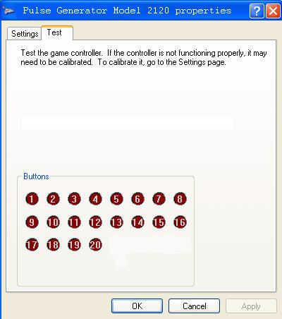
Lets go through a few assignments so you can fully understand what's happening. With your attention turned to the J1 Header, you will find the wires connected to Pins 1 and 2 (that is the pin with the RED "DOT" (see above) and pin #2 is directlr across from #1. With the "Pulse Generator Model 2120 Properties" window showing (calibration window), "short" these two pins together. When shorted, the #1 Red Ball will light in the window from about 1/4 second. Remove the short; the light will be pulse for another 1/4 second. Now short the third and fourth wires on the J1 Ribbon Cable. The #2 Red Button will flash. Short the #4 and #5 pin, Red Buitton #5 will flash. Get the idea?
When shorting every 2 wires, the corresponding Red Button will flash until you come to Pin numbers 15 and 16. From the above TABLE, you can see that Pins 15 to 20 are not connected to any circuitry. So these 6 Pins should be skipped.
The remaining 3 switches (Switch #8, Switch #9 and Switch #10) are connected to Pins 21 & 22 - Pins 23 & 24 - Pins 25 & 26. The last Toggle Switch on the J1 Cable is #10. Pins 29/30 and Pins 33/34 are Voltage and Common Ground connections. These pins come in handy if your Switch Design requires voltage to power an integrated circuit, LED, small relay ect. The 5 Volt DC is present on BOTH Pins 29 and 30 while the Common Ground is connected to Pins 33 and 34.
If your avionics panel requires 10 Switch or less, you can stop there. But if you need more then 10 switches, you need now turn your attention to the J2 Header and take note of the required connections from the TABLE seen above.
If Pins 1 (Red Dot) and 2 of the J2 are shorted together, the #20 Button will flash. Shorting Pins 3 and 4 will flash the #19 Button and so on until you reach Pins 21 to 34. These Pins are not connected to any circuitry, so they are considered to be "OPEN" Circuits.
The wiring of Toggle Switches to the 2120 needs 2 wires for every switch. This is 1 control wire and 1 Common GROUND for every toggle. Below is a table showing the relationship between the J1 and J2 connections.
The Control Wires from the J1 Header are located at:
PINS 2, 4, 6, 8, 10, 12, 14, then starts up again at: 22, 24, 26
The Control Wires from the J2 Header are located at:
PINS 1, 3, 5, 7, 9, 11, 13, 15, 17, 19
If you want multiple LEDs, just wire up the additional LEDs as shown above. But this time, make the +5VDC a common connection for all switches. The additional toggle switches are to be connected to the 2120's J1 and J2 as previously discussed.
When wired, just mount the Toggle Switch onto the panel but with the orientation when the toggle is UP, the LED turns ON. That's It!
When wired, just mount the Toggle Switch onto the panel but with the orientation when the toggle is UP, the LED turns ON. That's It!
Alternative LED Switch Wiring:
Attention International Customers
If you live outside of the U.S. & Canada and wish to purchase this item: Please email us your complete shipping address. We will be more then happy to email you the required shipping Fees.
Any Over Payments are Quickly REFUNDED via PayPal.
For International Sales, Please read the
Terms & Conditions for Worldwide Shipping
Click Here to eMail us:
DesktopAviator@USA.com

Older Model board shown
Older Model board shown

From the photo above, you can see the J1 and J2 connectors of the 2120. The connector on the left is designated J1, while the connector on the right is J2. J1 & J2 are both 2x17 male "Headers" giving you 34 pins for each connector. Note the "RED" DOT on each of the Headers, The "RED" Dot indicates that this pin is Position #1. The pin to the right of pin 1 is Position #2. To make sense of this unusual pinout arrangement; take a look at the next photo.
Wiring LEDs to the 2120 Added 5-01-2009
I've received a number of emails asking how to wire an LED indicator light to the 2120 using the SPST Toggle Switch. Well, here it is!
Below is a simple schematic on how to just that. All you need is a 330 ohm 1/4 or 1/2 watt carbon resistor and either a RED or GREEN LED. Seeing that the LED will be mounted above the switch it is an easy job to wire the components.
Solder a short piece of wire from the FLAT end of the LED to the Top terminal of the Toggle Switch. Now, take the 330 ohm resistor and solder it to the ROUND SIDE OF THE LED. LEDs are a polarity sensitive components and can only be installed one way. If not, you run the risk of distroying the LED.
Now, the other side of the 330 ohm resistor needs to be connected to +5VDC. This voltage can be "stolen" from the computer's USB Port via the 2120 board at the location indicated on the schematic below.
Also note that the Toggle switch terminals must also be connected to the 2120's J1 and J2 connectors. So using the 2-pin female connectors that came with your purchase, solder the two terminals of the toggle switch to the 2-pin connector.
Now place the 2-pin connector at J1 pin #1 - #2 (RED Dot). Now, with the 2120 connected to your computer's USB Port, flip the toggle switch. The LED will go ON and OFF. If the LED remains ON at all times; just remove the 2-pin connector from the 2120 board and reconnect it but this time "flip" the connector around.
Wiring LED Toggle Switch to the 2120